In this tutorial I’ll discuss about configuration dynamic routing ospf with single area. Before we start, you can read on the previous article for OSPF area https://www.taufiknurhuda.web.id/2022/03/09/ospf-area/
The following is topology are used :
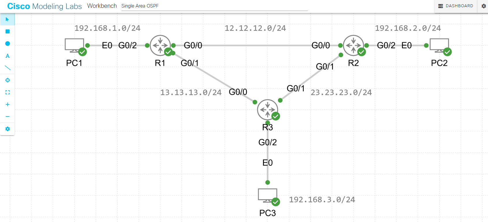
First, configuration the ip address on routers :
IP Address configuration R1 :
R1(config)#int g0/0
R1(config-if)#ip add 12.12.12.1 255.255.255.0
R1(config-if)#no sh
R1(config-if)#exit
R1(config)#int g0/1
R1(config-if)#ip add 13.13.13.1 255.255.255.0
R1(config-if)#no shut
R1(config-if)#exit
R1(config)#int g0/2
R1(config-if)#ip add 192.168.1.1 255.255.255.0
R1(config-if)#no shut
R1(config-if)#exit
IP Address configuration R2 :
R2(config)#int g0/0
R2(config-if)#ip add 12.12.12.2 255.255.255.0
R2(config-if)#no shut
R2(config-if)#exit
R2(config)#int g0/1
R2(config-if)#ip add 23.23.23.1 255.255.255.0
R2(config-if)#no shut
R2(config-if)#exit
R2(config)#int g0/2
R2(config-if)#ip add 192.168.2.1 255.255.255.0
R2(config-if)#exit
R2(config)#
IP Address configuration R3 :
R3(config)#int g0/0
R3(config-if)#ip add 13.13.13.2 255.255.255.0
R3(config-if)#no shut
R3(config-if)#exit
R3(config)#int g0/1
R3(config-if)#ip add 23.23.23.2 255.255.255.0
R3(config-if)#no shut
R3(config-if)#exit
R3(config)#int g0/2
R3(config-if)#ip add 192.168.3.1 255.255.255.0
R3(config-if)#no shut
R3(config-if)#exit
R3(config)#
For the next, configuration ip address on each PC :
IP Address configuration PC1 :
auto eth0
iface eth0 inet static
address 192.168.1.2
netmask 255.255.255.0
gateway 192.168.1.1

PC1:~$ ifconfig
eth0 Link encap:Ethernet HWaddr 52:54:00:1C:EF:84
inet addr:192.168.1.2 Bcast:0.0.0.0 Mask:255.255.255.0
inet6 addr: fe80::5054:ff:fe1c:ef84/64 Scope:Link
IP Adress configuration PC2 :
auto eth0
iface eth0 inet static
address 192.168.2.2
netmask 255.255.255.0
gateway 192.168.2.1

PC2:~$ ifconfig
eth0 Link encap:Ethernet HWaddr 52:54:00:1F:AF:25
inet addr:192.168.2.2 Bcast:0.0.0.0 Mask:255.255.255.0
inet6 addr: fe80::5054:ff:fe1f:af25/64 Scope:Link
UP BROADCAST RUNNING MULTICAST MTU:1500 Metric:1
IP Address configuration PC3 :
auto eth0
iface eth0 inet static
address 192.168.3.2
netmask 255.255.255.0
gateway 192.168.3.1

PC3:~$ ifconfig
eth0 Link encap:Ethernet HWaddr 52:54:00:13:9B:6C
inet addr:192.168.3.2 Bcast:0.0.0.0 Mask:255.255.255.0
inet6 addr: fe80::5054:ff:fe13:9b6c/64 Scope:Link
Make sure connetion on PCs to each router connected. Do a test ping to ip gateway :
PC1:~$ ping 192.168.1.1
PING 192.168.1.1 (192.168.1.1): 56 data bytes
64 bytes from 192.168.1.1: seq=0 ttl=42 time=2.781 ms
64 bytes from 192.168.1.1: seq=1 ttl=42 time=0.896 ms
64 bytes from 192.168.1.1: seq=2 ttl=42 time=0.889 ms
64 bytes from 192.168.1.1: seq=3 ttl=42 time=1.546 ms
PC2:~$ ping 192.168.2.1 PING 192.168.2.1 (192.168.2.1): 56 data bytes 64 bytes from 192.168.2.1: seq=0 ttl=42 time=1.004 ms 64 bytes from 192.168.2.1: seq=1 ttl=42 time=1.413 ms 64 bytes from 192.168.2.1: seq=2 ttl=42 time=1.374 ms 64 bytes from 192.168.2.1: seq=3 ttl=42 time=1.392 ms
PC3:~$ ping 192.168.3.1
PING 192.168.3.1 (192.168.3.1): 56 data bytes
64 bytes from 192.168.3.1: seq=0 ttl=42 time=2.955 ms
64 bytes from 192.168.3.1: seq=1 ttl=42 time=1.093 ms
64 bytes from 192.168.3.1: seq=2 ttl=42 time=0.955 ms
64 bytes from 192.168.3.1: seq=3 ttl=42 time=1.439 ms
Connection test is successfull, pc can be reach to each router gateway but it’s doesn’t connected yet to other network because there are no routing configuration. So let’s configuration dynamic routing with OSPF. Because we only need to configure single area, so it’s only need to use area 0 (backbone area).
Configuration OSPF on R1 :
R1(config)#router ospf 1
R1(config-router)#network 12.12.12.0 0.0.0.255 area 0
R1(config-router)#network 13.13.13.0 0.0.0.255 area 0
R1(config-router)#network 192.168.1.0 0.0.0.255 area 0
R1(config-router)#exit
Configuration OSPF on R2 :
R2(config)#router ospf 1
R2(config-router)#network 12.12.12.0 0.0.0.255 area 0
R2(config-router)#network 23.23.23.0 0.0.0.255 area 0
R2(config-router)#network 192.168.2.0 0.0.0.255 area 0
R2(config-router)#exit
Configuration OSPF on R3 :
R3(config)#router ospf 1
R3(config-router)#network 13.13.13.0 0.0.0.255 area 0
R3(config-router)#network 23.23.23.0 0.0.0.255 area 0
R3(config-router)#network 192.168.3.0 0.0.0.255 area 0
R3(config-router)#exit
After configuration ospf is done, on each router you can make sure a log which indicated adjacency is successfull and the routing ospf is already formed.
OSPF Log on R1 :
*Sep 4 06:23:17.740: %OSPF-5-ADJCHG: Process 1, Nbr 192.168.2.1 on GigabitEthernet0/0 from LOADING to FULL, Loading Done
*Sep 4 06:25:15.249: %OSPF-5-ADJCHG: Process 1, Nbr 192.168.3.1 on GigabitEthernet0/1 from LOADING to FULL, Loading Done
OSPF log on R2 :
*Sep 4 06:23:04.693: %OSPF-5-ADJCHG: Process 1, Nbr 192.168.1.1 on GigabitEthernet0/0 from LOADING to FULL, Loading Done
*Sep 4 06:25:45.327: %OSPF-5-ADJCHG: Process 1, Nbr 192.168.3.1 on GigabitEthernet0/1 from LOADING to FULL, Loading Done
OSPF log on R3 :
*Sep 4 06:25:17.918: %OSPF-5-ADJCHG: Process 1, Nbr 192.168.1.1 on GigabitEthernet0/0 from LOADING to FULL, Loading Done
*Sep 4 06:26:01.532: %OSPF-5-ADJCHG: Process 1, Nbr 192.168.2.1 on GigabitEthernet0/1 from LOADING to FULL, Loading Done
Next you can check the neighbor router ospf
Look at the capture bellow, on R1 there are two neighbor where it’s neighbor for R2 (192.168.2.1) and R3 (192.168.3.1) so it’s mean R1 is success to formed the ospf routing protocol with R2 & R3. Then also Look at ospf neighbor on R2 and R3, it’s same that routers is success.
R1#show ip ospf neighborNeighbor ID Pri State Dead Time Address Interface 192.168.3.1 1 FULL/BDR 00:00:39 13.13.13.2 GigabitEthernet0/1 192.168.2.1 1 FULL/BDR 00:00:35 12.12.12.2 GigabitEthernet0/0 R1#
R2#show ip ospf neighbor

Neighbor ID Pri State Dead Time Address Interface
192.168.3.1 1 FULL/BDR 00:00:39 23.23.23.2 GigabitEthernet0/1
192.168.1.1 1 FULL/DR 00:00:33 12.12.12.1 GigabitEthernet0/0
R2#
R3#show ip ospf neighbor

Neighbor ID Pri State Dead Time Address Interface
192.168.2.1 1 FULL/DR 00:00:38 23.23.23.1 GigabitEthernet0/1
192.168.1.1 1 FULL/DR 00:00:33 13.13.13.1 GigabitEthernet0/0
R3#
Show routing table on R1.
Look at on routing table bellow. you can see from R1 towards network 23.23.23.0/24 is load balanced via 13.13.13.2 and 12.12.12.2 as gateway. network 192.168.2.0/24 via 12.12.12.2 as gateway and last for network 192.168.3.0/24 via 13.13.13.2 as gateway.
R1#show ip route ospf
Codes: L - local, C - connected, S - static, R - RIP, M - mobile, B - BGP
       D - EIGRP, EX - EIGRP external, O - OSPF, IA - OSPF inter area
       N1 - OSPF NSSA external type 1, N2 - OSPF NSSA external type 2
       E1 - OSPF external type 1, E2 - OSPF external type 2
       i - IS-IS, su - IS-IS summary, L1 - IS-IS level-1, L2 - IS-IS level-2
       ia - IS-IS inter area, * - candidate default, U - per-user static route
       o - ODR, P - periodic downloaded static route, H - NHRP, l - LISP
       a - application route
       + - replicated route, % - next hop override, p - overrides from PfR

Gateway of last resort is not set

       23.0.0.0/24 is subnetted, 1 subnets
O    23.23.23.0 [110/2] via 13.13.13.2, 00:06:48, GigabitEthernet0/1
                [110/2] via 12.12.12.2, 00:08:56, GigabitEthernet0/0
O    192.168.2.0/24 [110/2] via 12.12.12.2, 00:08:46, GigabitEthernet0/0
O    192.168.3.0/24 [110/2] via 13.13.13.2, 00:06:27, GigabitEthernet0/1
R1#
Show route table on R2.
Look at on routing table bellow, from R2 towards 13.13.13.0/24 is load balanced via 23.23.23.2 and 12.12.12.1 as gateway. Network 192.168.1.0/24 via 12.12.12.1 as gateway and the last is network 192.168.3.0/24 route via 23.23.23.2 as gateway.
R2#show ip route ospf
Codes: L - local, C - connected, S - static, R - RIP, M - mobile, B - BGP
       D - EIGRP, EX - EIGRP external, O - OSPF, IA - OSPF inter area
       N1 - OSPF NSSA external type 1, N2 - OSPF NSSA external type 2
       E1 - OSPF external type 1, E2 - OSPF external type 2
       i - IS-IS, su - IS-IS summary, L1 - IS-IS level-1, L2 - IS-IS level-2
       ia - IS-IS inter area, * - candidate default, U - per-user static route
       o - ODR, P - periodic downloaded static route, H - NHRP, l - LISP
       a - application route
       + - replicated route, % - next hop override, p - overrides from PfR

Gateway of last resort is not set

     13.0.0.0/24 is subnetted, 1 subnets
O      13.13.13.0 [110/2] via 23.23.23.2, 00:07:16, GigabitEthernet0/1
                  [110/2] via 12.12.12.1, 00:10:03, GigabitEthernet0/0
O      192.168.1.0/24 [110/2] via 12.12.12.1, 00:10:03, GigabitEthernet0/0
O      192.168.3.0/24 [110/2] via 23.23.23.2, 00:06:56, GigabitEthernet0/1
R2#
Show routing table on R3.
Look at on routing table bellow, as you can see from R3 towards network 12.12.12.0/24 is load balanced via 23.23.23.1 and 13.13.13.1 as gateway. Network 192.168.1.0/24 via 13.13.13.1 as gateway and last for network 192.168.2.0/24 via 23.23.23.1 as gateway.
R3#show ip route ospf
Codes: L - local, C - connected, S - static, R - RIP, M - mobile, B - BGP
       D - EIGRP, EX - EIGRP external, O - OSPF, IA - OSPF inter area
       N1 - OSPF NSSA external type 1, N2 - OSPF NSSA external type 2
       E1 - OSPF external type 1, E2 - OSPF external type 2
       i - IS-IS, su - IS-IS summary, L1 - IS-IS level-1, L2 - IS-IS level-2
       ia - IS-IS inter area, * - candidate default, U - per-user static route
       o - ODR, P - periodic downloaded static route, H - NHRP, l - LISP
       a - application route
       + - replicated route, % - next hop override, p - overrides from PfR

Gateway of last resort is not set

      12.0.0.0/24 is subnetted, 1 subnets
O       12.12.12.0 [110/2] via 23.23.23.1, 00:07:38, GigabitEthernet0/1
                   [110/2] via 13.13.13.1, 00:08:26, GigabitEthernet0/0
O       192.168.1.0/24 [110/2] via 13.13.13.1, 00:08:26, GigabitEthernet0/0
O       192.168.2.0/24 [110/2] via 23.23.23.1, 00:07:38, GigabitEthernet0/1
R3#
Now try to test ping from PC1 to PC2 on R2 and PC3 on R3.
As you can see bellow, PC1 is successfull connected to PC2 and PC3.
PC1:~$ ping 192.168.2.2
PING 192.168.2.2 (192.168.2.2): 56 data bytes
64 bytes from 192.168.2.2: seq=0 ttl=42 time=2.087 ms
64 bytes from 192.168.2.2: seq=1 ttl=42 time=2.069 ms
64 bytes from 192.168.2.2: seq=2 ttl=42 time=1.459 ms
--- 192.168.2.2 ping statistics ---
3 packets transmitted, 3 packets received, 0% packet loss
round-trip min/avg/max = 1.459/1.871/2.087 ms
PC1:~$
PC1:~$ ping 192.168.3.2
PING 192.168.3.2 (192.168.3.2): 56 data bytes
64 bytes from 192.168.3.2: seq=0 ttl=42 time=1.983 ms
64 bytes from 192.168.3.2: seq=1 ttl=42 time=1.912 ms
64 bytes from 192.168.3.2: seq=2 ttl=42 time=1.518 ms
64 bytes from 192.168.3.2: seq=3 ttl=42 time=1.980 ms
--- 192.168.3.2 ping statistics ---
4 packets transmitted, 4 packets received, 0% packet loss
round-trip min/avg/max = 1.518/1.848/1.983 ms
Now traceroute from PC1 to PC2 and PC3 so you can see the routing path towards other networks.
PC1:~$ traceroute 192.168.2.2
traceroute to 192.168.2.2 (192.168.2.2), 30 hops max, 46 byte packets
1 192.168.1.1 (192.168.1.1) 0.898 ms 0.972 ms 0.787 ms
2 12.12.12.2 (12.12.12.2) 1.652 ms 1.716 ms 1.658 ms
3 192.168.2.2 (192.168.2.2) 1.579 ms 1.318 ms 3.565 ms
PC1:~$ traceroute 192.168.3.2
traceroute to 192.168.3.2 (192.168.3.2), 30 hops max, 46 byte packets
1 192.168.1.1 (192.168.1.1) 0.844 ms 1.148 ms 0.769 ms
2 13.13.13.2 (13.13.13.2) 1.659 ms 1.737 ms 1.593 ms
3 192.168.3.2 (192.168.3.2) 1.599 ms 1.398 ms 1.924 ms
PC1:~$
Do the ping test and traceroute from PC2 and PC3 also.
PC2:~$ ping 192.168.1.2
PING 192.168.1.2 (192.168.1.2): 56 data bytes
64 bytes from 192.168.1.2: seq=0 ttl=42 time=1.641 ms
64 bytes from 192.168.1.2: seq=1 ttl=42 time=1.676 ms
64 bytes from 192.168.1.2: seq=2 ttl=42 time=1.617 ms
--- 192.168.1.2 ping statistics ---
4 packets transmitted, 4 packets received, 0% packet loss
round-trip min/avg/max = 1.617/1.686/1.812 ms
PC2:~$ ping 192.168.3.2
PING 192.168.3.2 (192.168.3.2): 56 data bytes
64 bytes from 192.168.3.2: seq=0 ttl=42 time=1.373 ms
64 bytes from 192.168.3.2: seq=1 ttl=42 time=2.584 ms
64 bytes from 192.168.3.2: seq=2 ttl=42 time=5.618 ms
--- 192.168.3.2 ping statistics ---
4 packets transmitted, 4 packets received, 0% packet loss
round-trip min/avg/max = 1.373/2.884/5.618 ms
PC2:~$ traceroute 192.168.1.2
traceroute to 192.168.1.2 (192.168.1.2), 30 hops max, 46 byte packets
1 192.168.2.1 (192.168.2.1) 0.921 ms 1.099 ms 1.355 ms
2 12.12.12.1 (12.12.12.1) 1.578 ms 1.981 ms 1.397 ms
3 192.168.1.2 (192.168.1.2) 1.287 ms 1.481 ms 1.175 ms

PC2:~$ traceroute 192.168.3.2
traceroute to 192.168.3.2 (192.168.3.2), 30 hops max, 46 byte packets
1 192.168.2.1 (192.168.2.1) 0.919 ms 0.955 ms 0.850 ms
2 23.23.23.2 (23.23.23.2) 1.443 ms 1.449 ms 1.598 ms
3 192.168.3.2 (192.168.3.2) 1.311 ms 3.188 ms 2.996 ms
PC2:~$
PC2:~$ ping 192.168.1.2
PING 192.168.1.2 (192.168.1.2): 56 data bytes
64 bytes from 192.168.1.2: seq=0 ttl=42 time=1.641 ms
64 bytes from 192.168.1.2: seq=1 ttl=42 time=1.676 ms
64 bytes from 192.168.1.2: seq=2 ttl=42 time=1.617 ms
64 bytes from 192.168.1.2: seq=3 ttl=42 time=1.812 ms
--- 192.168.1.2 ping statistics ---
4 packets transmitted, 4 packets received, 0% packet loss
round-trip min/avg/max = 1.617/1.686/1.812 ms
PC2:~$ ping 192.168.3.2
PING 192.168.3.2 (192.168.3.2): 56 data bytes
64 bytes from 192.168.3.2: seq=0 ttl=42 time=1.373 ms
64 bytes from 192.168.3.2: seq=1 ttl=42 time=2.584 ms
64 bytes from 192.168.3.2: seq=2 ttl=42 time=5.618 ms
64 bytes from 192.168.3.2: seq=3 ttl=42 time=1.962 ms
--- 192.168.3.2 ping statistics ---
4 packets transmitted, 4 packets received, 0% packet loss
round-trip min/avg/max = 1.373/2.884/5.618 ms
PC2:~$ traceroute 192.168.1.2
traceroute to 192.168.1.2 (192.168.1.2), 30 hops max, 46 byte packets
1 192.168.2.1 (192.168.2.1) 0.921 ms 1.099 ms 1.355 ms
2 12.12.12.1 (12.12.12.1) 1.578 ms 1.981 ms 1.397 ms
3 192.168.1.2 (192.168.1.2) 1.287 ms 1.481 ms 1.175 ms

PC2:~$ traceroute 192.168.3.2
traceroute to 192.168.3.2 (192.168.3.2), 30 hops max, 46 byte packets
1 192.168.2.1 (192.168.2.1) 0.919 ms 0.955 ms 0.850 ms
2 23.23.23.2 (23.23.23.2) 1.443 ms 1.449 ms 1.598 ms
3 192.168.3.2 (192.168.3.2) 1.311 ms 3.188 ms 2.996 ms
PC2:~$
Configuration OSPF Single area is successfull.
organic tea for sale online
Great article! Your insights are very valuable, and the way you presented the information made it easy to understand. I appreciate the time and effort you put into researching and writing this. It’s a great resource for anyone interested in this topic.