At the previous article I’ve discuss about How to Configure OSPF Single Area. And in this tutorial I’ll discuss about how to configuration OSPF Multiple Area.
The Following is the topology are used :
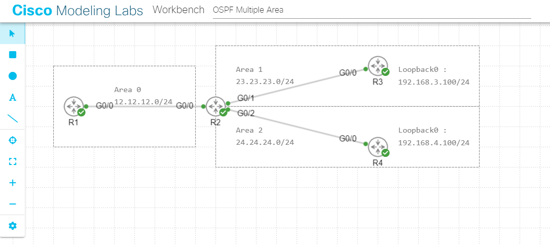
Once configure the OSPF Single area, we only need to advertise each router with backbone area (Area). But when configured the Multiple area we need to add some regular area on router that configured multi area. Look at the topology above, R1 in the Backbone area (Area 0), R2 is running with multiple area which run the Backbone area (area 0) and Regular area (Area 1 & Area 2). And then R3 is in the regular area (area 1) also R4 in the regular area (area 2).
In this lab we used the loopback ip for R3 and R4 as the network tested.
OK first, let’s configure the ip address on each routers.
Configure IP Address R1 :
R1(config)#int g0/0
R1(config-if)#ip add 12.12.12.1 255.255.255.0
R1(config-if)#no shut
R1(config-if)#exit
Configure IP Address R2 :
R2(config)#int g0/0
R2(config-if)#ip add 12.12.12.2 255.255.255.0
R2(config-if)#no shut
R2(config-if)#exit
R2(config)#int g0/1
R2(config-if)#ip add 23.23.23.1 255.255.255.0
R2(config-if)#no shut
R2(config-if)#exit
R2(config)#int g0/2
R2(config-if)#ip add 24.24.24.1 255.255.255.0
R2(config-if)#no shut
R2(config-if)#exit
R2(config)#
Configure IP Adddress R3 :
R3(config)#int g0/0
R3(config-if)#ip add 23.23.23.2 255.255.255.0
R3(config-if)#no shut
R3(config-if)#exit
R3(config)#
R3(config)#int lo0
R3(config-if)#ip add 192.168.3.100 255.255.255.0
R3(config-if)#exit
R3(config)#
Configure IP Address R4:
R4(config)#int g0/0
R4(config-if)#ip add 24.24.24.2 255.255.255.0
R4(config-if)#no shut
R4(config-if)#exit
R4(config)#
R4(config)#int lo0
R4(config-if)#
R4(config-if)#ip add 192.168.4.100 255.255.255.0
R4(config-if)#exit
R4(config)#
Now, Configure the route ospf for each routers :
Configure OSPF on R1 :
R1(config)#router ospf 1
R1(config-router)#network 12.12.12.0 0.0.0.255 area 0
R1(config-router)#exit
R1(config)#
Configure OSPF on R2. Look at the configuration bellow, because R2 is running with multi area, so you must configuration each network with the area.
Refer based on topology, network 12.12.12.0/24 is in the backbone area (area0), network 23.23.23.0/24 is in the area 1 and last for network 24.24.24.0/24 is in the area 2.
R2(config)#router ospf 1
R2(config-router)#network 12.12.12.0 0.0.0.255 area 0
R2(config-router)#network 23.23.23.0 0.0.0.255 area 1
R2(config-router)#network 24.24.24.0 0.0.0.255 area 2
R2(config-router)#exit
R2(config-router)#
Configure OSPF on R3. Because R3 is a regular area, so configure area with area 1.
R3(config)#router ospf 1
R3(config-router)#network 23.23.23.0 0.0.0.255 area 1
R3(config-router)#network 192.168.3.0 0.0.0.255 area 1
R3(config-router)#exit
R3(config-router)#
Configure OSPF on R4. And also for R4 is a regular area, configure it with area 2.
R4(config)#router ospf 1
R4(config-router)#network 24.24.24.0 0.0.0.255 area 2
R4(config-router)#network 192.168.4.0 0.0.0.255 area 2
R4(config-router)#exit
R4(config-router)#
After that, Makesure the adjacency area successfull for all routers. You can see a log on each routers.
R1(config)#
*Sep 7 15:46:46.033: %OSPF-5-ADJCHG: Process 1, Nbr 24.24.24.1 on GigabitEthernet0/0 from LOADING to FULL, Loading Done
R2(config-router)#
*Sep 7 15:46:45.529: %OSPF-5-ADJCHG: Process 1, Nbr 12.12.12.1 on GigabitEthernet0/0 from LOADING to FULL, Loading Done
*Sep 7 15:49:00.703: %OSPF-5-ADJCHG: Process 1, Nbr 192.168.3.100 on GigabitEthernet0/1 from LOADING to FULL, Loading Done
*Sep 7 15:50:06.326: %OSPF-5-ADJCHG: Process 1, Nbr 192.168.4.100 on GigabitEthernet0/2 from LOADING to FULL, Loading Done
R3(config-router)#
*Sep 7 15:49:01.668: %OSPF-5-ADJCHG: Process 1, Nbr 24.24.24.1 on GigabitEthernet0/0 from LOADING to FULL, Loading Done
R4(config-router)#
*Sep 7 15:50:06.202: %OSPF-5-ADJCHG: Process 1, Nbr 24.24.24.1 on GigabitEthernet0/0 from LOADING to FULL, Loading Done
Show the neighbor on each routers :
Router R1 is success to achieve full adjacency with R2
R1#show ip ospf neighbor

Neighbor ID    Pri    State      Dead Time    Address      Interface
24.24.24.1     1      FULL/BDR   00:00:35     12.12.12.2    GigabitEthernet0/0
R1#
Router R2 is success to achieve full adjacency with R1, R3 and R4
R2#show ip ospf neighbor

Neighbor ID     Pri    State      Dead Time    Address      Interface
12.12.12.1      1      FULL/DR    00:00:31     12.12.12.1   GigabitEthernet0/0
192.168.3.100   1      FULL/BDR   00:00:31     23.23.23.2   GigabitEthernet0/1
192.168.4.100   1      FULL/BDR   00:00:32     24.24.24.2   GigabitEthernet0/2
R2#
Last R3 and R4 also success to achieve full adjacency with R2 :
R3#show ip ospf nei

Neighbor ID    Pri    State     Dead Time    Address      Interface
24.24.24.1     1      FULL/DR   00:00:37     23.23.23.1   GigabitEthernet0/0
R3#
R4#show ip ospf neighbor Neighbor ID Pri State Dead Time Address Interface 24.24.24.1 1 FULL/DR 00:00:33 24.24.24.1 GigabitEthernet0/0 R4#
Show the IP Route on R1 :
R1#show ip route ospf
Codes: L - local, C - connected, S - static, R - RIP, M - mobile, B - BGP
       D - EIGRP, EX - EIGRP external, O - OSPF, IA - OSPF inter area
       N1 - OSPF NSSA external type 1, N2 - OSPF NSSA external type 2
       E1 - OSPF external type 1, E2 - OSPF external type 2
       i - IS-IS, su - IS-IS summary, L1 - IS-IS level-1, L2 - IS-IS level-2
       ia - IS-IS inter area, * - candidate default, U - per-user static route
       o - ODR, P - periodic downloaded static route, H - NHRP, l - LISP
       a - application route
       + - replicated route, % - next hop override, p - overrides from PfR

Gateway of last resort is not set

       23.0.0.0/24 is subnetted, 1 subnets
O IA     23.23.23.0 [110/2] via 12.12.12.2, 00:23:48, GigabitEthernet0/0
       24.0.0.0/24 is subnetted, 1 subnets
O IA     24.24.24.0 [110/2] via 12.12.12.2, 00:23:32, GigabitEthernet0/0
       192.168.3.0/32 is subnetted, 1 subnets
O IA     192.168.3.100 [110/3] via 12.12.12.2, 00:22:17, GigabitEthernet0/0
       192.168.4.0/32 is subnetted, 1 subnets
O IA     192.168.4.100 [110/3] via 12.12.12.2, 00:21:08, GigabitEthernet0/0
R1#
Look at the routing table on R1 above, you cans ee the flag for each routing is IA. which mean an Inter Area. Commonly an OSPF has two entry route is Inter Area and Intra Area.
Inter Area as you can see above is an entry route that’s coming from different area, Definitely is a route network from area 1 & area 2 for this lab. And for Intra Area is an entry route that’s coming from the same area.
Then you can make sure the configured area on router with show ip route command. Look at the bottom line output for R1 is only configured with Backbone Area (0).
R1#show ip ospf
......output ommited..
Reference bandwidth unit is 100 mbps
Area BACKBONE(0)
Number of interfaces in this area is 1
Area has no authentication
SPF algorithm last executed 00:27:52.000 ago
SPF algorithm executed 4 times
Area ranges are
Number of LSA 7. Checksum Sum 0x038B7A
Number of opaque link LSA 0. Checksum Sum 0x000000
Number of DCbitless LSA 0
Number of indication LSA 0
Number of DoNotAge LSA 0
Flood list length 0

R1#
Show ip route on R2 . You can see the Intra Area on R2 for R3 & R4 route network. Why is that ? because the R2 is running in Multiple Area, so it’s part of backbone area, area1 & area2.
R2#show ip route ospf
Codes: L - local, C - connected, S - static, R - RIP, M - mobile, B - BGP
       D - EIGRP, EX - EIGRP external, O - OSPF, IA - OSPF inter area
       N1 - OSPF NSSA external type 1, N2 - OSPF NSSA external type 2
       E1 - OSPF external type 1, E2 - OSPF external type 2
       i - IS-IS, su - IS-IS summary, L1 - IS-IS level-1, L2 - IS-IS level-2
       ia - IS-IS inter area, * - candidate default, U - per-user static route
       o - ODR, P - periodic downloaded static route, H - NHRP, l - LISP
       a - application route
       + - replicated route, % - next hop override, p - overrides from PfR

Gateway of last resort is not set

      192.168.3.0/32 is subnetted, 1 subnets
O        192.168.3.100 [110/2] via 23.23.23.2, 00:28:28, GigabitEthernet0/1
      192.168.4.0/32 is subnetted, 1 subnets
O        192.168.4.100 [110/2] via 24.24.24.2, 00:27:20, GigabitEthernet0/2
R2#
Confirm the area on R2 with show ip ospf command. See the R2 is part of backbone area, Area 1 & Area 2.
R2#show ip ospf
....output ommited..
Reference bandwidth unit is 100 mbps
Area BACKBONE(0)
Number of interfaces in this area is 1
Area has no authentication
SPF algorithm last executed 00:30:08.139 ago
SPF algorithm executed 4 times
Area ranges are
Number of LSA 7. Checksum Sum 0x038B7A
Number of opaque link LSA 0. Checksum Sum 0x000000
Number of DCbitless LSA 0
Number of indication LSA 0
Number of DoNotAge LSA 0
Flood list length 0
Area 1
Number of interfaces in this area is 1
Area has no authentication
SPF algorithm last executed 00:28:52.391 ago
SPF algorithm executed 5 times
Area ranges are
Number of LSA 6. Checksum Sum 0x03E274
Number of opaque link LSA 0. Checksum Sum 0x000000
Number of DCbitless LSA 0
Number of indication LSA 0
Number of DoNotAge LSA 0
Flood list length 0
Area 2
Number of interfaces in this area is 1
Area has no authentication
SPF algorithm last executed 00:27:44.004 ago
SPF algorithm executed 4 times
Area ranges are
Number of LSA 6. Checksum Sum 0x02B395
Number of opaque link LSA 0. Checksum Sum 0x000000
Number of DCbitless LSA 0
Number of indication LSA 0
Number of DoNotAge LSA 0
Flood list length 0

R2#
Show the ip route on R3 & confirm R3 OSPF area. Look at on routing table R3 is an Inter Area because the route network is coming from different area.
R3#show ip route ospf
Codes: L - local, C - connected, S - static, R - RIP, M - mobile, B - BGP
       D - EIGRP, EX - EIGRP external, O - OSPF, IA - OSPF inter area
       N1 - OSPF NSSA external type 1, N2 - OSPF NSSA external type 2
       E1 - OSPF external type 1, E2 - OSPF external type 2
       i - IS-IS, su - IS-IS summary, L1 - IS-IS level-1, L2 - IS-IS level-2
       ia - IS-IS inter area, * - candidate default, U - per-user static route
       o - ODR, P - periodic downloaded static route, H - NHRP, l - LISP
       a - application route
       + - replicated route, % - next hop override, p - overrides from PfR

Gateway of last resort is not set

      12.0.0.0/24 is subnetted, 1 subnets
O IA     12.12.12.0 [110/2] via 23.23.23.1, 00:31:01, GigabitEthernet0/0
      24.0.0.0/24 is subnetted, 1 subnets
O IA     24.24.24.0 [110/2] via 23.23.23.1, 00:31:01, GigabitEthernet0/0
      192.168.4.0/32 is subnetted, 1 subnets
O IA     192.168.4.100 [110/3] via 23.23.23.1, 00:29:31, GigabitEthernet0/0
R3#
R3#show ip ospf
....output ommited..
Reference bandwidth unit is 100 mbps
Area 1
Number of interfaces in this area is 2 (1 loopback)
Area has no authentication
SPF algorithm last executed 00:30:54.981 ago
SPF algorithm executed 3 times
Area ranges are
Number of LSA 6. Checksum Sum 0x03DA78
Number of opaque link LSA 0. Checksum Sum 0x000000
Number of DCbitless LSA 0
Number of indication LSA 0
Number of DoNotAge LSA 0
Flood list length 0

R3#
Then Show ip route for R4. This router also has an Inter Area because network route is coming from different area.
R4#show ip route ospf
Codes: L - local, C - connected, S - static, R - RIP, M - mobile, B - BGP
       D - EIGRP, EX - EIGRP external, O - OSPF, IA - OSPF inter area
       N1 - OSPF NSSA external type 1, N2 - OSPF NSSA external type 2
       E1 - OSPF external type 1, E2 - OSPF external type 2
       i - IS-IS, su - IS-IS summary, L1 - IS-IS level-1, L2 - IS-IS level-2
       ia - IS-IS inter area, * - candidate default, U - per-user static route
       o - ODR, P - periodic downloaded static route, H - NHRP, l - LISP
       a - application route
       + - replicated route, % - next hop override, p - overrides from PfR

Gateway of last resort is not set

       12.0.0.0/24 is subnetted, 1 subnets
O IA      12.12.12.0 [110/2] via 24.24.24.1, 00:31:17, GigabitEthernet0/0
       23.0.0.0/24 is subnetted, 1 subnets
O IA      23.23.23.0 [110/2] via 24.24.24.1, 00:31:17, GigabitEthernet0/0
       192.168.3.0/32 is subnetted, 1 subnets
O IA      192.168.3.100 [110/3] via 24.24.24.1, 00:31:17, GigabitEthernet0/0
R4#
R4#show ip ospf
...output ommited..
Reference bandwidth unit is 100 mbps
Area 2
Number of interfaces in this area is 2 (1 loopback)
Area has no authentication
SPF algorithm last executed 00:31:13.707 ago
SPF algorithm executed 3 times
Area ranges are
Number of LSA 6. Checksum Sum 0x02AD98
Number of opaque link LSA 0. Checksum Sum 0x000000
Number of DCbitless LSA 0
Number of indication LSA 0
Number of DoNotAge LSA 0
Flood list length 0

R4#
And for the last testing, do a ping and traceroute from R2 towards loopback ip on R3 & R4.
R1#ping 192.168.3.100
Type escape sequence to abort.
Sending 5, 100-byte ICMP Echos to 192.168.3.100, timeout is 2 seconds:
!!!!!
Success rate is 100 percent (5/5), round-trip min/avg/max = 2/2/2 ms
R1#ping 192.168.4.100
Type escape sequence to abort.
Sending 5, 100-byte ICMP Echos to 192.168.4.100, timeout is 2 seconds:
!!!!!
Success rate is 100 percent (5/5), round-trip min/avg/max = 1/1/2 ms
R1#traceroute 192.168.3.100
Type escape sequence to abort.
Tracing the route to 192.168.3.100
VRF info: (vrf in name/id, vrf out name/id)
1 12.12.12.2 2 msec 2 msec 1 msec
2 23.23.23.2 2 msec 2 msec *
R1#traceroute 192.168.4.100
Type escape sequence to abort.
Tracing the route to 192.168.4.100
VRF info: (vrf in name/id, vrf out name/id)
1 12.12.12.2 1 msec 2 msec 1 msec
2 24.24.24.2 3 msec 2 msec *
R1#
Ping and Traceroute are successfull. Network can be reach.