Hello everyone, in this article I’ll discuss about how to configure VLAN on Fortigate firewall. On the operational network, if we only use single ip it’s only need to configured on direct interface. But when we need to extend/add multiple subnet under fortigate we can accomplish with VLAN configuration..
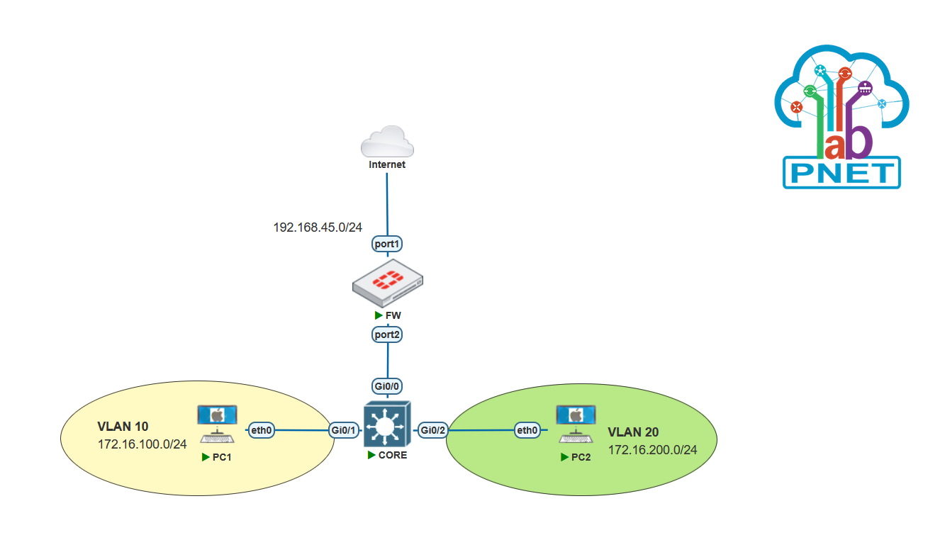
Here’s the topology are used. on LAN network we need to configured two segments which is VLAN 10 and VLAN 20. For the switch device I use Cisco for the Core Switch.
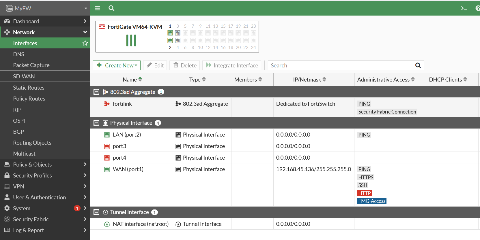
First Select on Network -> Interfaces, Then Create New.
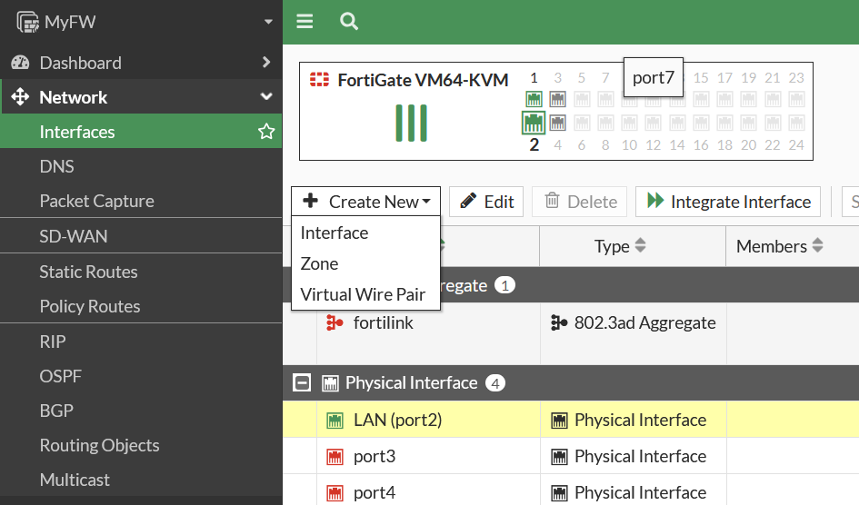
Then Select Interface
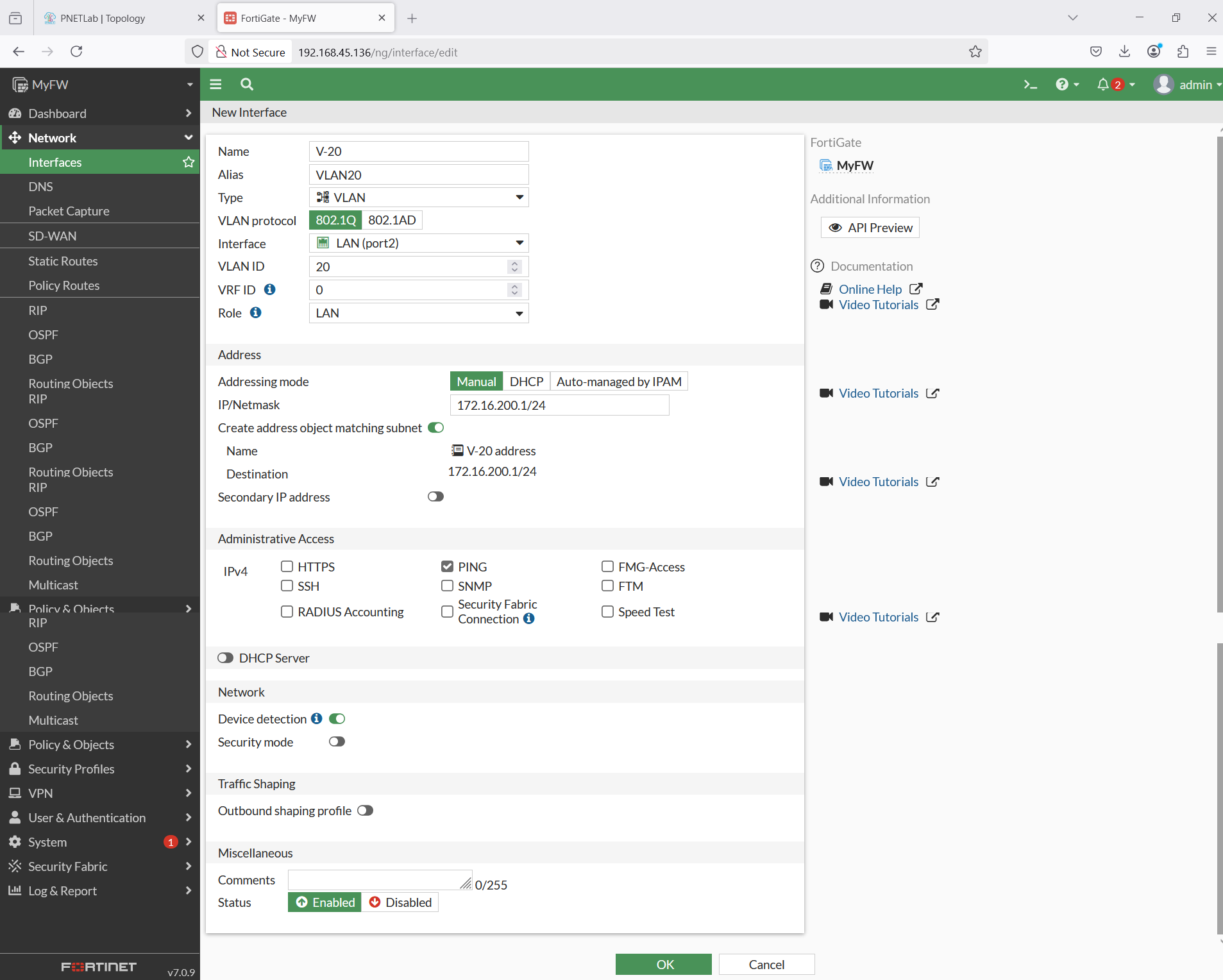
After that Configure for VLAN10. Protocol use for 802.1Q, interface LAN(port2), Role use for LAN.
On the Address section configure manual ip address for VLAN10.

Then configure for VLAN 20
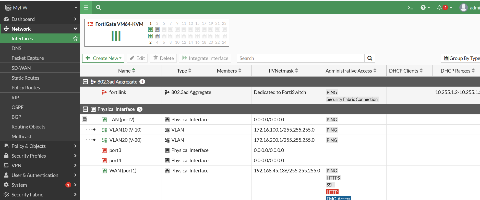
After VLAN created, It’s will be appears under the LAN interface as shown bellow.
After configure VLAN on fortigate, let’s move to the switch configuration.
Configure for the VLAN first :
CORE(config)#vlan 10
CORE(config-vlan)#name V-10
CORE(config-vlan)#exit
CORE(config)#vlan 20
CORE(config-vlan)#name V-20
CORE(config-vlan)#exit
CORE(config)#
Then verify the vlan configuration. As the shown bellow, VLAN 10 and VLAN 20 is already created.
CORE#show vlan brief

VLAN Name                             Status    Ports
---- -------------------------------- --------- -------------------------------
1    default                          active    Gi0/0, Gi0/1, Gi0/2, Gi0/3
                                                Gi1/0, Gi1/1, Gi1/2, Gi1/3
10   V-10                             active
20   V-20                             active
1002 fddi-default                     act/unsup
1003 token-ring-default               act/unsup
1004 fddinet-default                  act/unsup
1005 trnet-default                    act/unsup
CORE#
Next, Configure the interface that connect to the Fortigate. Set the interface as trunk port.
CORE(config)#int g0/0
CORE(config-if)#switchport trunk encapsulation dot1q
CORE(config-if)#switchport mode trunk
CORE(config-if)#exit
Then, Configuration on port g0/1 which connect to PC1 as access vlan 10.
CORE(config)#int g0/1
CORE(config-if)#switchport mode access
CORE(config-if)#switchport access vlan 10
CORE(config-if)#exit
After that configure on port g0/2 which connect to PC2 as access vlan 20.
CORE(config)#int g0/2
CORE(config-if)#switchport mode access
CORE(config-if)#switchport access vlan 20
CORE(config-if)#end
CORE#
Verify the vlan configuration. As the shown bellow, interface G0/1 already become vlan access 10 and G0/2 is already become vlan access 20.
CORE#show vlan brief
VLAN Name                             Status    Ports
---- -------------------------------- --------- -------------------------------
1    default                          active    Gi0/3, Gi1/0, Gi1/1, Gi1/2
                                                Gi1/3
10   V-10                             active    Gi0/1
20   V-20                             active    Gi0/2
1002 fddi-default                     act/unsup
1003 token-ring-default               act/unsup
1004 fddinet-default                  act/unsup
1005 trnet-default                    act/unsup
CORE#
Next, configure and verify ip address for PC1
PC1> ip 172.16.100.2/24 172.16.100.1
Checking for duplicate address...
PC1 : 172.16.100.2 255.255.255.0 gateway 172.16.100.1
PC1> show ip
NAME        : PC1[1]
IP/MASK     : 172.16.100.2/24
GATEWAY     : 172.16.100.1
DNS         : 1.1.1.1
MAC         : 00:50:79:66:68:20
LPORT       : 20000
RHOST:PORT  : 127.0.0.1:3000
MTU         : 1500
And also configure & verify ip address for PC2
PC2> ip 172.16.200.2/24 172.16.200.1
Checking for duplicate address...
PC2 : 172.16.200.2 255.255.255.0 gateway 172.16.200.1
PC2> show ip NAME : PC2[1] IP/MASK : 172.16.200.2/24 GATEWAY : 172.16.200.1 DNS : 1.1.1.1 MAC : 00:50:79:66:68:21 LPORT : 20000 RHOST:PORT : 127.0.0.1:30000 MTU : 1500
Then test connection from PC1 to interface VLAN 10 fortigate
PC1> ping 172.16.100.1
84 bytes from 172.16.100.1 icmp_seq=1 ttl=255 time=2.334 ms
84 bytes from 172.16.100.1 icmp_seq=2 ttl=255 time=2.186 ms
84 bytes from 172.16.100.1 icmp_seq=3 ttl=255 time=2.428 ms
Test connection from PC2 to interface VLAN 20 fortigate
PC2> ping 172.16.200.1
84 bytes from 172.16.200.1 icmp_seq=1 ttl=255 time=2.660 ms
84 bytes from 172.16.200.1 icmp_seq=2 ttl=255 time=2.612 ms
84 bytes from 172.16.200.1 icmp_seq=3 ttl=255 time=3.592 ms
Connection test for 1 segment is already success. Now try to access across the network. As shown bellow the PC1 can’t connect to PC2 and vice versa.
PC1> ping 172.16.200.2
172.16.200.2 icmp_seq=1 timeout
172.16.200.2 icmp_seq=2 timeout
172.16.200.2 icmp_seq=3 timeout
PC2> ping 172.16.100.2
172.16.100.2 icmp_seq=1 timeout
172.16.100.2 icmp_seq=2 timeout
172.16.100.2 icmp_seq=3 timeout
To solved that issue, create Firewall policy to permit access between the VLAN10.
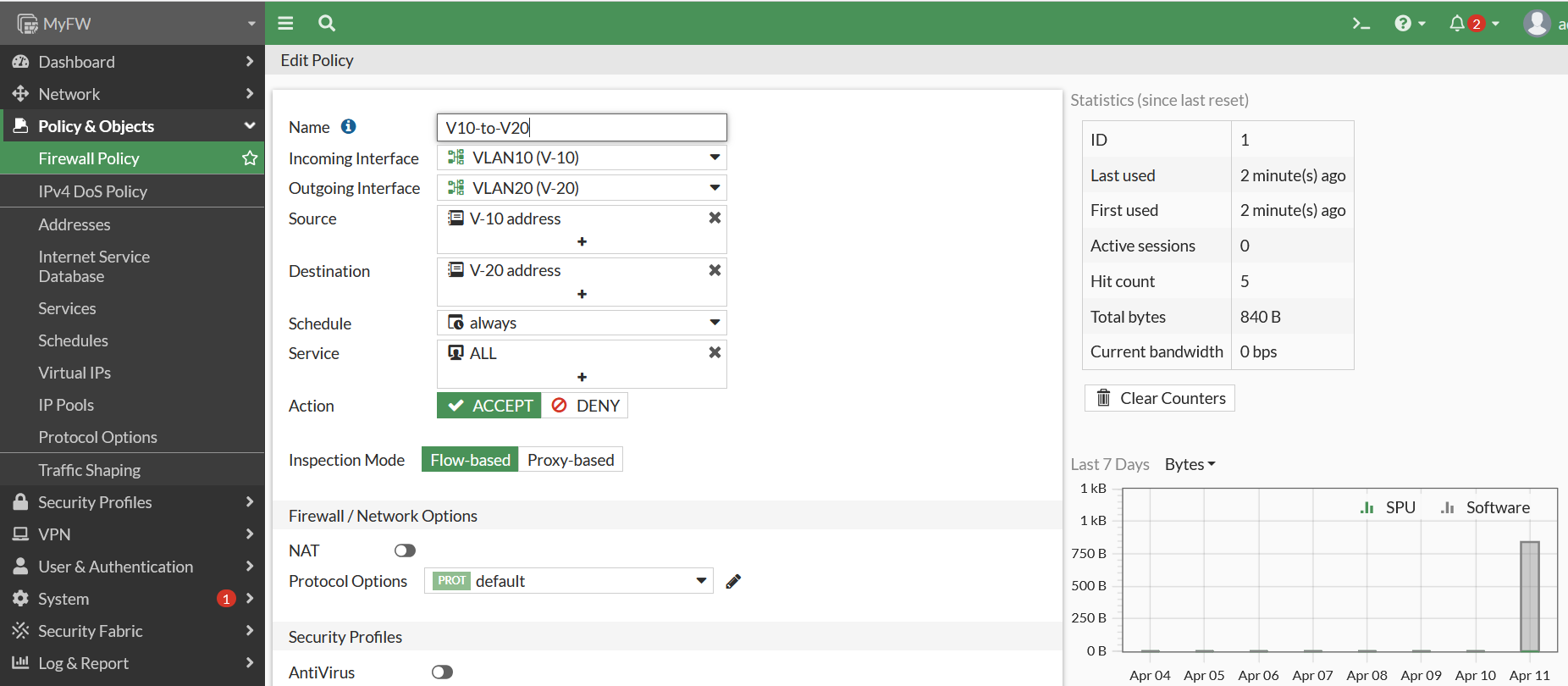
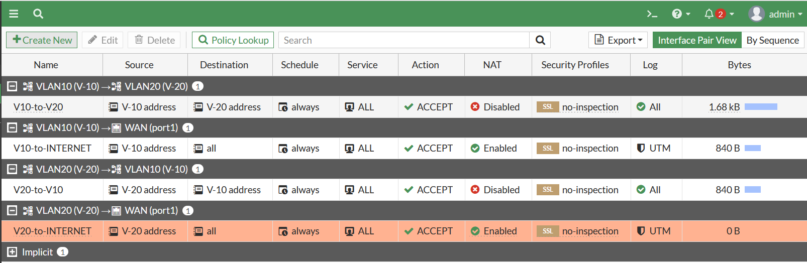
Create firewall policy to permit VLAN10 to VLAN20
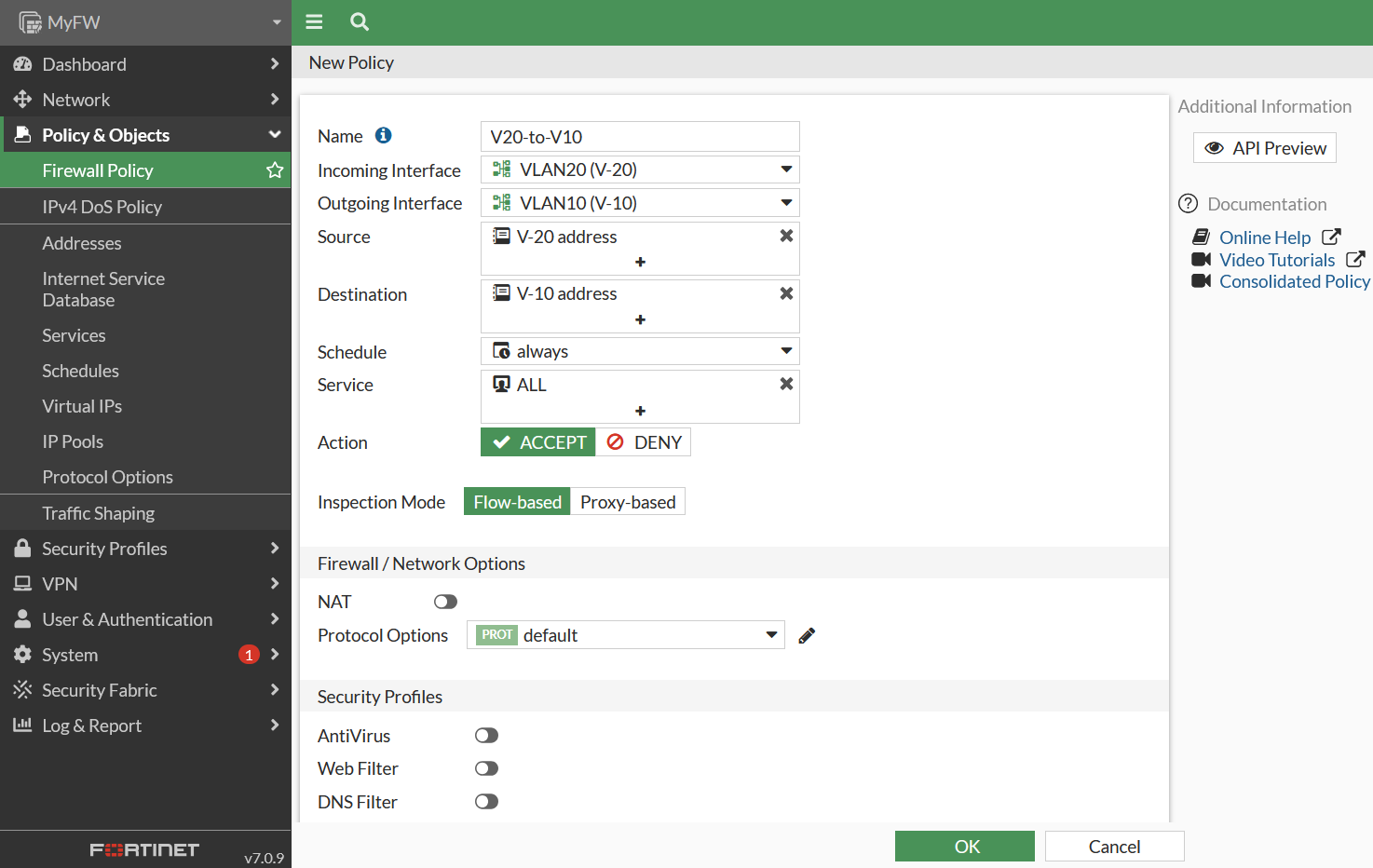
Create Firewall Policy to permit VLAN20 to VLAN10.
Then test ping again. the ping test between PC1 and PC2 is already successful.
PC1> ping 172.16.200.2
84 bytes from 172.16.200.2 icmp_seq=1 ttl=63 time=6.522 ms
84 bytes from 172.16.200.2 icmp_seq=2 ttl=63 time=4.514 ms
84 bytes from 172.16.200.2 icmp_seq=3 ttl=63 time=4.306 ms
PC2> ping 172.16.100.2
84 bytes from 172.16.100.2 icmp_seq=1 ttl=63 time=3.924 ms
84 bytes from 172.16.100.2 icmp_seq=2 ttl=63 time=5.505 ms
84 bytes from 172.16.100.2 icmp_seq=3 ttl=63 time=4.112 ms
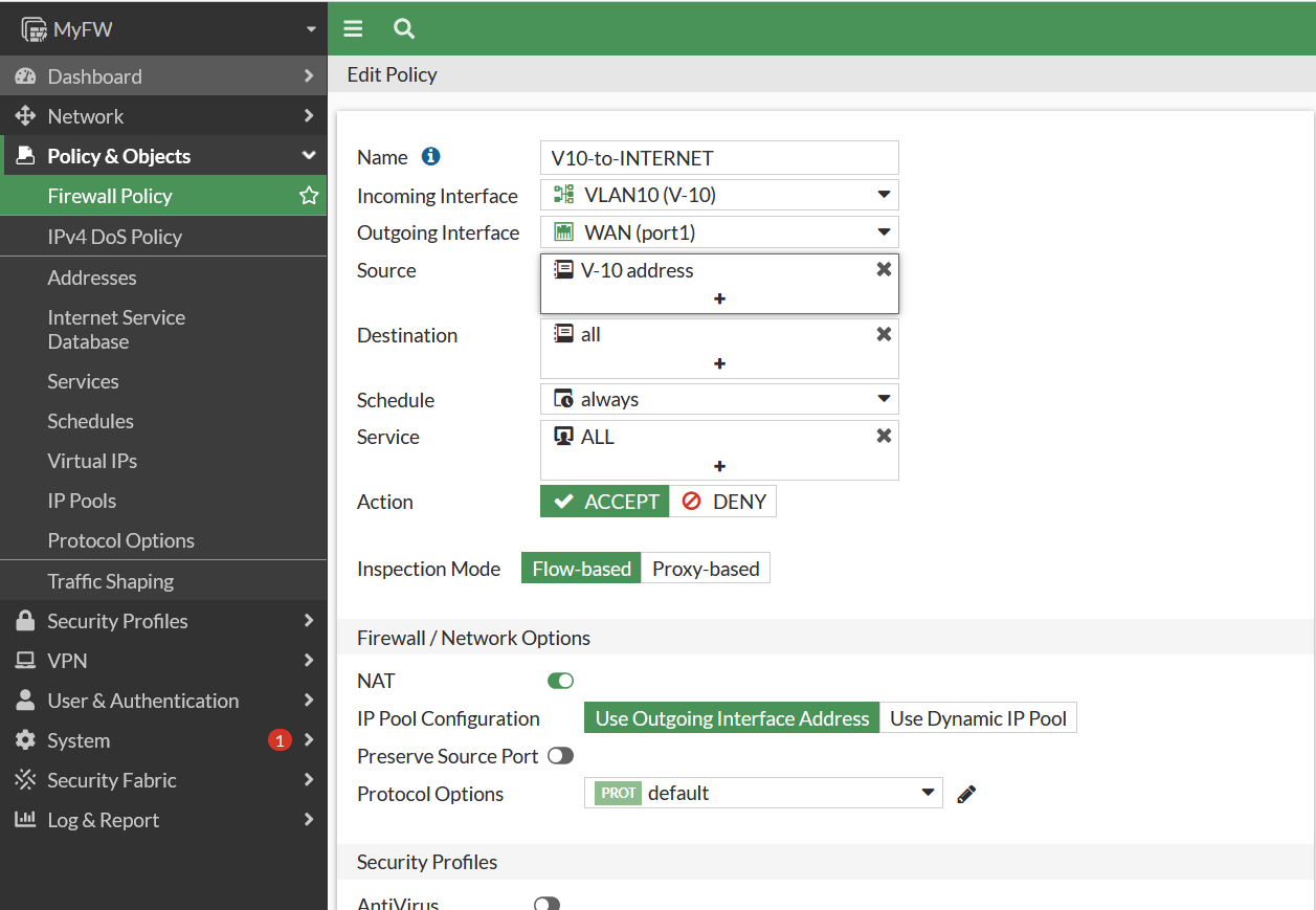
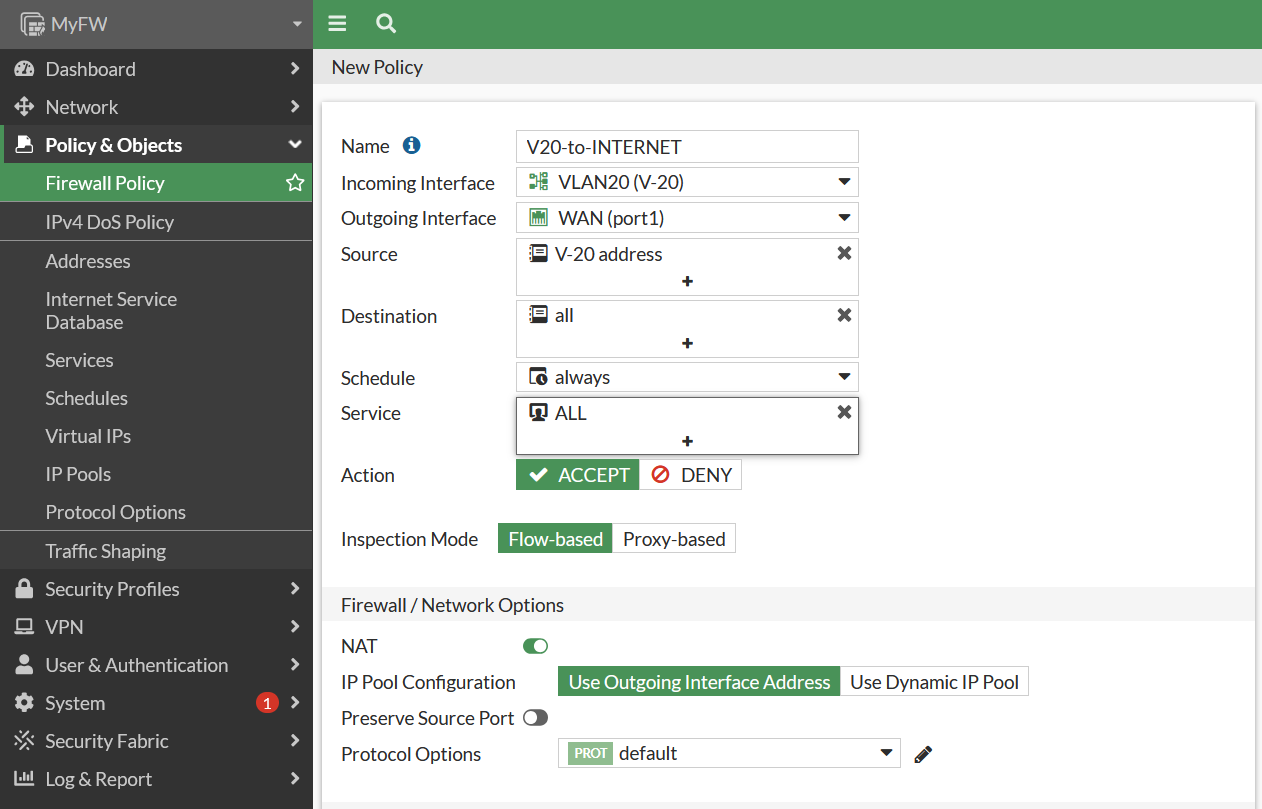
Okay last create firewall NAT to permit VLAN10 and VLAN20 segment through internet connection.
Ping test for PC1 & PC2 to internet is already successful.
PC1> ping 8.8.8.8
84 bytes from 8.8.8.8 icmp_seq=1 ttl=254 time=5.172 ms
84 bytes from 8.8.8.8 icmp_seq=2 ttl=254 time=3.300 ms
84 bytes from 8.8.8.8 icmp_seq=3 ttl=254 time=3.770 ms
PC2> ping 8.8.8.8
84 bytes from 8.8.8.8 icmp_seq=1 ttl=254 time=6.915 ms
84 bytes from 8.8.8.8 icmp_seq=2 ttl=254 time=4.130 ms
84 bytes from 8.8.8.8 icmp_seq=3 ttl=254 time=3.625 ms